


Since my last entry, some things have changed. Initially I wanted to build an RF sensing circuit that would feed signal readings to the NodeMCU, but due to technical (surface mounted component soldering) and budget complications (some components over $20USD, several of these needed) I had to come up with a slightly different idea.
Design Complications
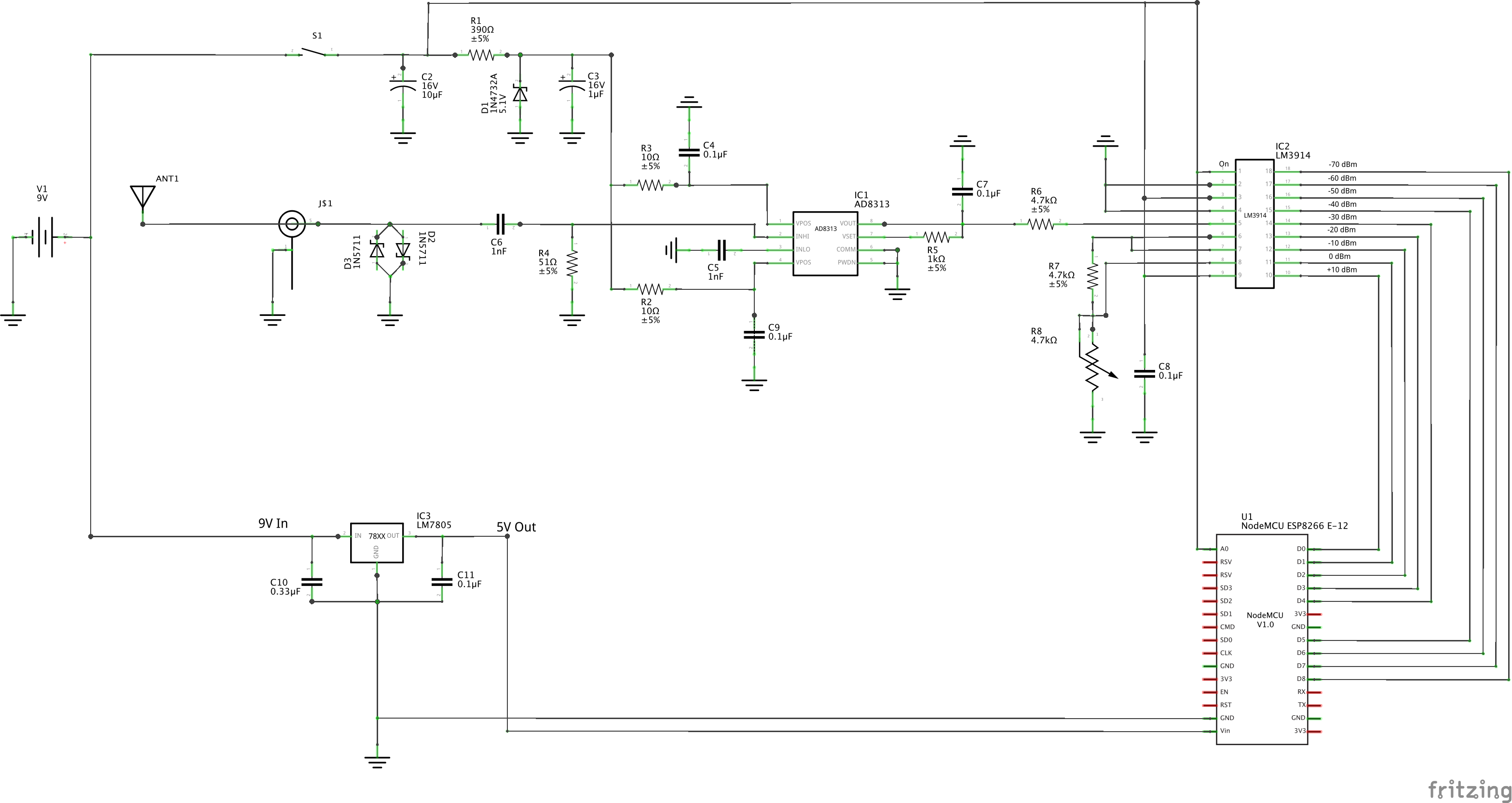
My preliminary sensor design was meant to encode the RF power readings into 9 possible outcomes (-70dBm to +10dBm in increments of 10dBm), output which was meant to interface directly with the NodeMCU using the Digital Pins D0 to D8:
But after some quick testing I realized I could not use all these pins for this purpose, and thought to myself “No problem, I’ll just use a Multiplexer to encode the readings into 4 bits”. So I embarked on the adventure of finding all the pieces to construct my circuit, including an appropriate Multiplexer. It was here that I realized that building this circuit would require some more money that what I had in mind, and that I would need special equipment (and additional training) to solder the surface-mounted components to their pin adapters. Not having the funds necessary for the components nor the time to perfect my soldering skills, I had to find a different way of making this work. I discussed some options with Prof. Schragger (who teaches my IoT Class), and decided that a viable alternative would be to simulate the behavior of the sensor.
Meet Edison
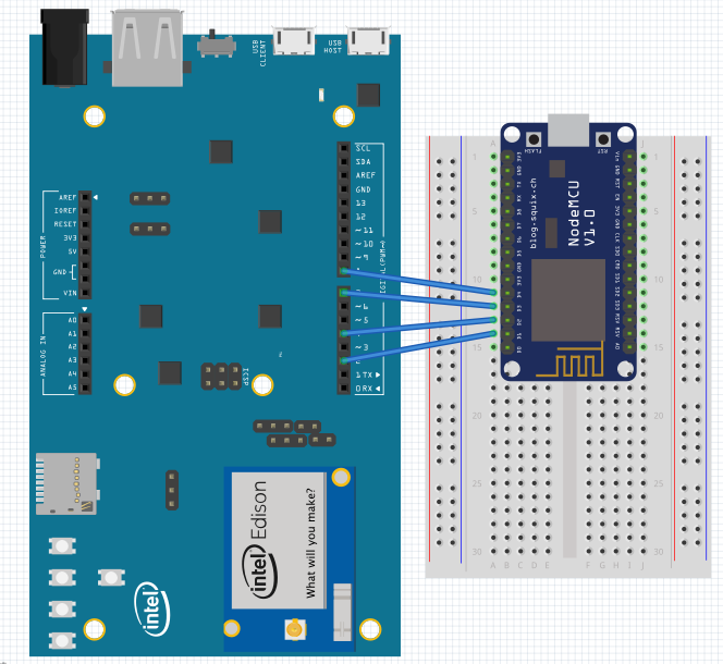
A couple of weeks back I attended an Arduino Hackathon, in which I received an Intel Edison Arduino Development Kit for participating. The Edison is Intel’s Atom (2 cores @500MHz) + Quark (1 core @100MHz) platform for IoT (which runs Linux), and this particular package came with the Arduino Breakout Board which makes the Edison compatible with the Arduino Uno R3 architecture. It also has built-in WiFi and Bluetooth LE capabilities and without the breakout board, the Edisson is no bigger than an SD card.

So having this interesting piece of hardware at my disposal, and it being equaly as easy to program as the NodeMCU (Arduino IDE), Eureka! I decided to use it to simulate the readings of the sensor I had decided not to build.
Simulation
Being compatible with the Arduino IDE, it was farily easy to implement the simulation I needed on the Edison. I decided to use GPIO Pins 2, 8, 7 and 8 to represent the four bits that would represent each of the 10 possible readings for the sensor (-70 to 10 + error).
Then I implemented the following code that would randomly output my predefined coded signals into the NodeMCU’s D1-D4 Pins:
[sourcecode language=”cpp”]
char* possibleMeasurements[] = {"0000","0001","0010","0011", "0100", "0101", "0110", "0111", "1000", "1001"};</code>
void setup() {
//Start Serial Console
Serial.begin(9600);
//Setup ditital pins as Outputs
pinMode(13, OUTPUT); //This will flash a board led indicating transmission
pinMode(2, OUTPUT); //This will be the most significant bit connectig to the NodeMCU’s D1 pin
pinMode(4, OUTPUT); //This will be the second most significant bit connectig to the NodeMCU’s D2 pin
pinMode(7, OUTPUT); //This will be the second least significant bit connectig to the NodeMCU’s D3 pin
pinMode(8, OUTPUT); //This will be the least significant bit connectig to the NodeMCU’s D4 pin
}
void loop() {
// put your main code here, to run repeatedly:
delay(100);
char* rfMeasurement = possibleMeasurements[random(0,10)];
//Serial.println(rfMeasurement);
//Turn on indicator LED
digitalWrite(13, HIGH);
if(rfMeasurement=="0000"){
digitalWrite(2, LOW);
digitalWrite(4, LOW);
digitalWrite(7, LOW);
digitalWrite(8, LOW);
Serial.println("No Measurement");
}
else if(rfMeasurement=="0001"){
digitalWrite(2, LOW);
digitalWrite(4, LOW);
digitalWrite(7, LOW);
digitalWrite(8, HIGH);
Serial.println("-70 dBm");
}
else if(rfMeasurement=="0010"){
digitalWrite(2, LOW);
digitalWrite(4, LOW);
digitalWrite(7, HIGH);
digitalWrite(8, LOW);
Serial.println("-60 dBm");
}
else if(rfMeasurement=="0011"){
digitalWrite(2, LOW);
digitalWrite(4, LOW);
digitalWrite(7, HIGH);
digitalWrite(8, HIGH);
Serial.println("-50 dBm");
}
else if(rfMeasurement=="0100"){
digitalWrite(2, LOW);
digitalWrite(4, HIGH);
digitalWrite(7, LOW);
digitalWrite(8, LOW);
Serial.println("-40 dBm");
}
else if(rfMeasurement=="0101"){
digitalWrite(2, LOW);
digitalWrite(4, HIGH);
digitalWrite(7, LOW);
digitalWrite(8, HIGH);
Serial.println("-30 dBm");
}
else if(rfMeasurement=="0110"){
digitalWrite(2, LOW);
digitalWrite(4, HIGH);
digitalWrite(7, HIGH);
digitalWrite(8, LOW);
Serial.println("-20 dBm");
}
else if(rfMeasurement=="0111"){
digitalWrite(2, LOW);
digitalWrite(4, HIGH);
digitalWrite(7, HIGH);
digitalWrite(8, HIGH);
Serial.println("-10 dBm");
}
else if(rfMeasurement=="1000"){
digitalWrite(2, HIGH);
digitalWrite(4, LOW);
digitalWrite(7, LOW);
digitalWrite(8, LOW);
Serial.println("0 dBm");
}
else if(rfMeasurement=="1001"){
digitalWrite(2, HIGH);
digitalWrite(4, LOW);
digitalWrite(7, LOW);
digitalWrite(8, HIGH);
Serial.println("+10 dBm");
}
else {
digitalWrite(2, HIGH);
digitalWrite(4, HIGH);
digitalWrite(7, HIGH);
digitalWrite(8, HIGH);
Serial.println("ERROR");
}
delay(2000); //Wait 2s to generate another reading (keeping the current reading on)
//Set all pins to low
digitalWrite(2, LOW);
digitalWrite(4, LOW);
digitalWrite(7, LOW);
digitalWrite(8, LOW);
//Turn of indicator LED
digitalWrite(13, LOW);
}
[/sourcecode]
The simulated RF readings behave correcty and are read by the NodeMCU. Expect another post detailing the rest of the project’s architecture and implementation soon.
As always, thanks for reading!
1 Pingback